In this article we'll show you how to connect your PiicoDev® modules to your favourite development platforms.
Connection Guides
To follow our PiicoDev guides for RPi Pico, it's best to have:
- A Raspberry Pi Pico (with pins soldered, facing down)
- PiicoDev Modules of your choice
- A PiicoDev adapter for Raspberry Pi Pico
- A PiicoDev Cable

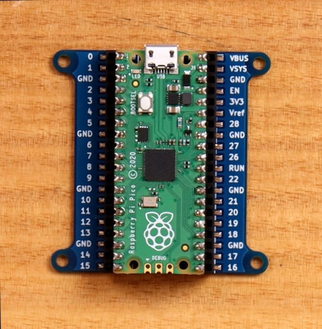
Step 1: Plug your Pico into the PiicoDev Expansion Board for Raspberry Pi Pico.
Make sure the USB socket is on the same side as the Expansion Board's larger, 2-pin connector. Pin 0 is the pin to the left of the USB connector.

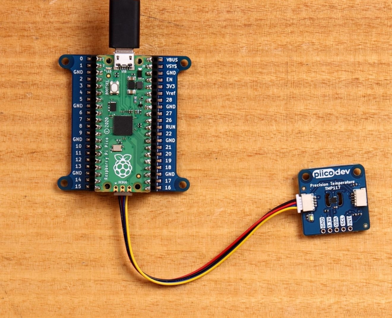
Step 2: Plug the PiicoDev cable into the Expansion Board's PiicoDev connector - that's the 4-pin connector at the bottom edge of the board.

Step 3: Connect the other end of the PiicoDev cable to your PiicoDev module. Each PiicoDev module has two connectors so you can daisy-chain modules - It doesn't matter which connector you choose.

Step 4: Finally, connect your RPi Pico to your computer with a USB lead
To follow our PiicoDev guides for Raspberry Pi, it's best to have:
- A Raspberry Pi (model 3, 4, Zero or Zero W)
- PiicoDev Modules of your choice
- A PiicoDev adapter for Raspberry Pi
- A PiicoDev Cable. 100mm or longer is best for the connection between the PiicoDev Adapter and the first PiicoDev module.
Step 1: Plug your PiicoDev adapter into the Raspberry Pi GPIO header. On a Raspberry Pi 4 Model B, the "Ethernet" arrow will point towards the Pi 4's ethernet connector. On a Pi 3 Model B, this will point to a USB socket instead.
Make sure the adapter is centered on the GPIO connector - that it is not shifted and plugging into the wrong pins.
Step 2: Plug the PiicoDev cable into one of the adapter sockets - it doesn't matter which one you choose.
Step 3: Connect the other end of the PiicoDev cable to your PiicoDev module. Each PiicoDev module has two connectors so you can daisy-chain modules - It doesn't matter which connector you choose.

To follow our PiicoDev guides for Micro:bit, it's best to have:
- A Micro:bit v2
- PiicoDev Modules of your choice
- A PiicoDev adapter for Micro:bit
- A PiicoDev Cable

Step 1: Fit the PiicoDev adapter for Microbit to your Micro:bit. Make sure the Sure the Micro:bit's buttons are facing up.

Step 2: Plug the PiicoDev cable into one of the adapter sockets

Step 3: Connect the other end of the PiicoDev cable to your PiicoDev module. Each PiicoDev module has two connectors so you can daisy-chain modules - It doesn't matter which connector you choose.
\
Step 4: Finally, connect your Micro:bit to your computer with a USB lead

Other Connection Methods
If you prefer working without PiicoDev adapters, there are a few other methods for connecting to your PiicoDev modules. These are a lot more freestyle, so you'll need to check your dev-board's datasheet to make sure you're connecting to the right pins.
Breadboard (no soldering, freestyle)
Some hardware you might find useful:
You can use a PiicoDev breadboard adapter or PiicoDev Prototyping Cable to connect with a PiicoDev module either directly or on a breadboard.. Make the power and I2C connections with your development board using some jumper wire and connect your PiicoDev device with a PiicoDev cable.

A PiicoDev Prototyping cable can make point-to-point connections either on a breadboard or directly to your dev-board.

Here you can see a breadboard adapter is being used with an Arduino Uno R3. The adapter brings a PiicoDev connector to the breadboard that connects to the Arduino via jumper wires
Breadboard (soldering, freestyle)
You can skip the PiicoDev breadboard adapter entirely and solder your own headers to the 2.54mm breakout on the bottom edge of every PiicoDev module.
Soldering (freestyle)
You can solder pins to your PiicoDev module and plug it into a breadboard, or you can use wires to solder the module directly to your development board of choice. This is a lot more freestyle - you're on your own for this one!
The minimum connections you need to make are for Power (3V3 and GND), Clock (SCL) and Data (SDA). Be sure to double-check these connections with your dev. board's datasheet.
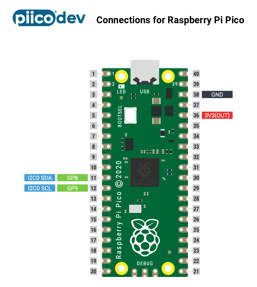
Technical Note - If you are proceeding with one of the freestyle options: Check your dev board documentation to find which pins (SDA, SCL) are used by default. Our PiicoDev packages use I2C0 by default on Raspberry Pi Pico and Micro:bit. On a Raspberry Pi SBC I2C1 is used by default.
Connecting Many Modules
PiicoDev Modules are daisy-chainable. That means you can connect several together in a string. Connecting many modules (more than six or so) can electrically overload the I2C communications bus - interrupting communications and putting your project on hold. If you intend to connect six or more modules at the same time, you can reduce the load on the I2C bus by cutting the I2C pullup resistors on some modules. This will effectively remove their load from the bus.

PiicoDev "Smart" Modules
Some PiicoDev modules are fitted with an "ID" switch and/or jumpers. These are PiicoDev Smart Modules. The easiest way to use a Smart Module is to leave its ID switches off and jumpers unsoldered. In this configuration (the "default state") the Smart Module can be initialised without any additional arguments. For example, to initialise a PiicoDev 3x RGB LED Module, your code might look like this
rgb = PiicoDev_RGB()
When multiple Smart Modules are on the same I2C bus, they must have unique ID configurations. For example, to drive two RGB LED modules, we could leave the first in the default state (with all ID switches/jumpers open), and on the second we could set the ID:1 switch ON.
Then our setup code would take the form below. Since the first module is in the default state we can initialise it as above. The second module is not in the default state, it has the ID:1 switch closed - we need to pass the id argument which is a list of the switches that are ON. In this case, only the first switch is on, so the first element in the list is 1:
rgbA = PiicoDev_RGB()
rgbB = PiicoDev_RGB( id=[1,0,0,0] )
Smart Modules only check their ID switches on powerup - you need to power-cycle your smart module if you change any of the switches.
Custom Address (Advanced users)
The id argument abstracts the I2C device address from the user. What's really going on behind the scenes is that all Smart Modules default to I2C address 0x08. The ID switches create a binary number (LSB=ID:1) that is added to 0x08 on power-up. For example, if switch ID:1 is ON, and ID:3 is soldered then the id argument would be id=[1,0,1,0] = 5, so the address will be 0x08 0x05 = 0x0D.
It is possible to set any address between 0x08->0x77 for a PiicoDev Smart Module in software. You might want to do this if you plan to exceed the maximum number of devices addressable with just the ID switches/jumpers alone, or if there would be an address collision otherwise.
To use a custom address, the device ID switches must be in the default state. Initialise the device as usual, and then call the setI2Caddr(newAddress) command where newAddress is a number between 0x08 and 0x77. An example is provided below. The ID switches must remain in the default state to use the custom address.
from PiicoDev_RGB import PiicoDev_RGB

leds = PiicoDev_RGB() # initialise the module
leds.setI2Caddr(0x55) # change the address to 0x55
Now, to use this device with the custom address, it must be initialised as follows:
leds = PiicoDev_RGB(addr=0x55)
If you forget what address you set a module to, the process to reset it is as follows:
- Remove power from the Smart Module
- Set any ID switch to ON
- Power up the Smart Module
- Remove power from the Smart Module
- Set the ID switches to the default state (all OFF)
The module address is now reset to factory default.

